
Scalable Planting Families - Makeup & Tips

Setting up a scalable planting family is quite complicated. There are loads of small ways to make mistakes that will lead to unwanted scaling behavior.
We understand that landscape and architectural firms will have their own visual preferences for each specific tree type (columnar, round, pyramidal, etc.) and most likely have their own 2D CAD blocks already in use.
The aim of this blog is simply to give the end user, or the poor soul who has been tasked with transferring their company’s CAD blocks into Revit, a general understanding of how to successfully use, update or create such Revit families.
If you haven’t tried out our scalable planting families yet, make sure to download the collection here.
Metadata
Let’s start by looking at the information provided by nurseries. This information covers things like soil and light conditions, planting locations and tree aesthetics, and can be found on nursery websites like Tree Ebb. It helps landscape architects choose which kind of tree they want to use and is also important for populating project schedules.
Fiorella Schiavo, the landscape architect and BIM expert who advised us on our scalable planting collection, showed us how she uses this type of information to ensure that projects have the correct trees or plants for their specific locations. For example, it’s crucial to check details such as the “Winter hardiness zone” and “PH range” before placing a tree into a project.
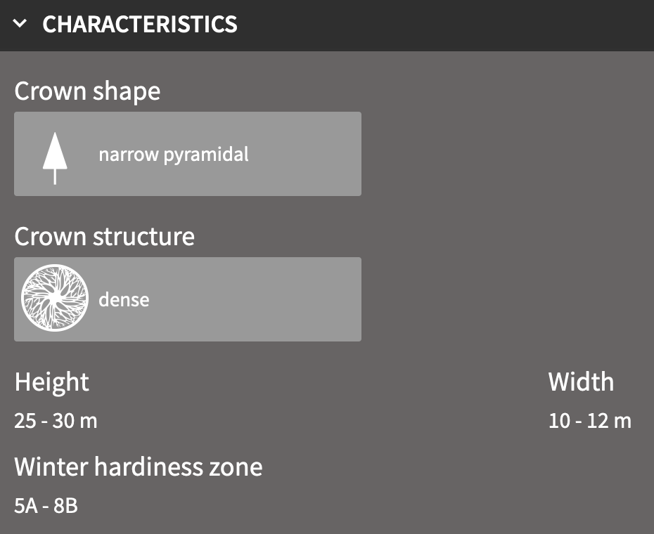
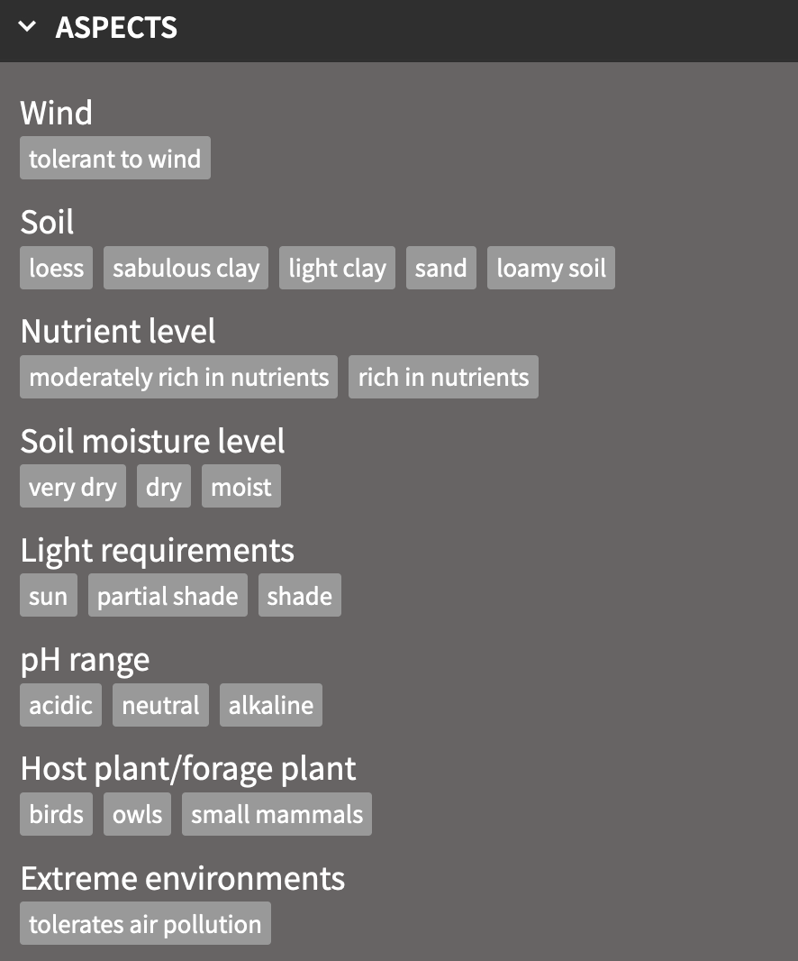
Nursery data for tree characteristics and aspects.
Makeup
As mentioned in the original blog post where we shared these families, I doubt our process would have gone so smoothly without access to the tutorials from RV Boost. In fact, it still wasn’t that easy even with the tutorials. But their video on the scalable Minotaur is great for showing the concept of scaling objects using planting families.
Normally we advise against the “over-nesting” of families, or nesting DWG blocks or any other kind of non-native Revit geometry. This is mainly due to the dramatic effect it can have on file size. In this case, however, the DWGs are necessary to achieve the desired scaling functionality.
Now, you might be wondering, “Why can’t we use Revit geometry for this?” After all, Revit is parametric and Revit-native components can easily be made to scale.
To be honest, our first attempt at creating these planting families involved a scalable Revit plan symbol that could flex and bring visual variations depending on size. This ended up taking a lot of time and work to make sure it didn’t break. It looked nice, but it wasn’t effectively customizable.
It became obvious that, while it’s theoretically possible to use native Revit geometry, it’s just not feasible at a large scale with many different types of trees or plants. The detail is also somewhat fixed. On the other hand, the 2D CAD blocks can easily be scaled, replaced and customized to suit the desired tree or plant.
Nesting
The planting family has a fairly complex nesting system, but we’ve done the hard work. So you, yes you, only need to take care of the DWGs you’d like to use, and then a couple of points to tie them into the main planting family.
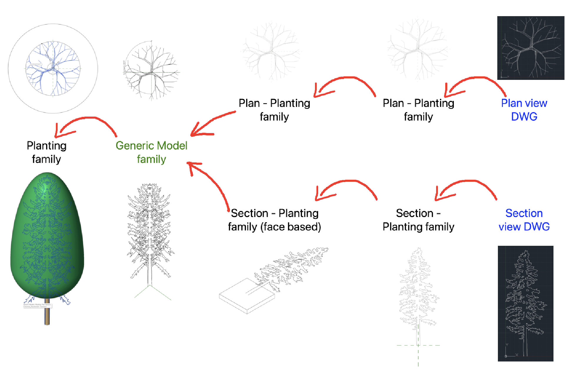
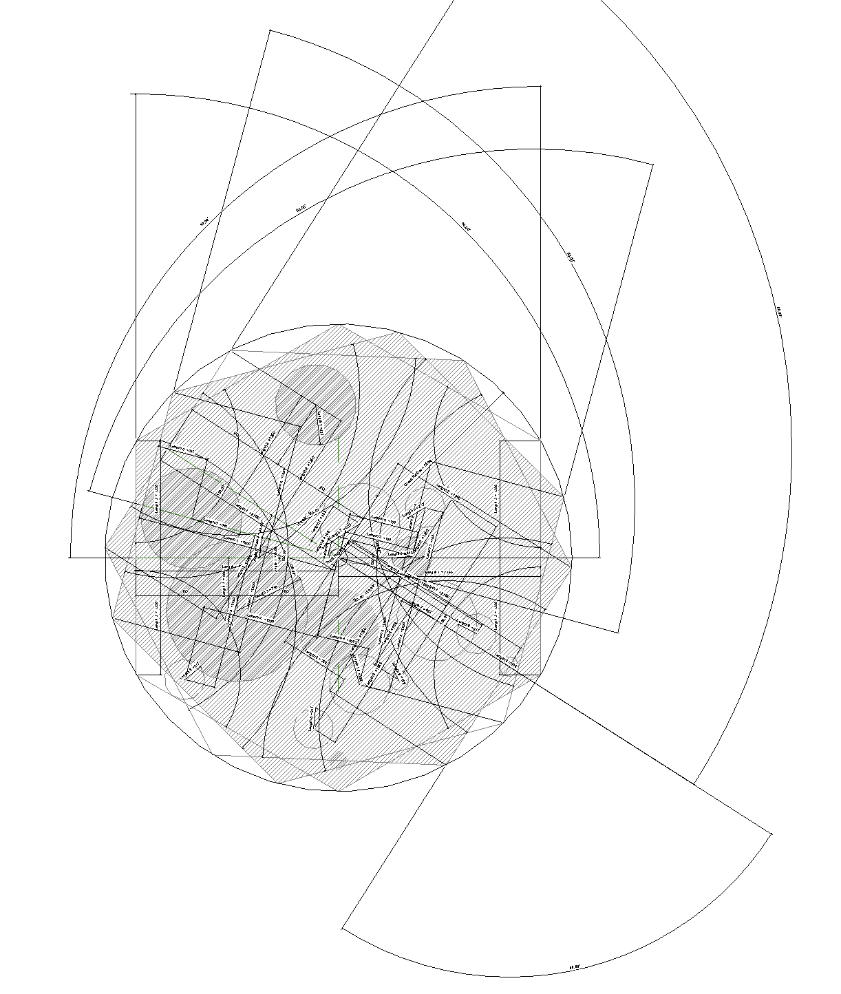
Our planting families allow the section DWGs to change the aspect ratio. Not only can they scale vertically like other planting families out there, but their scaling isn’t fixed to the ratio of the DWG. They can reduce in width from the original size.
This means they can maintain a better relationship with the crown diameter of the tree and hence the plan view. This is achieved by using a face-based planting family and nesting it onto reference lines that rotate to suit a reduced crown diameter from the origin size.
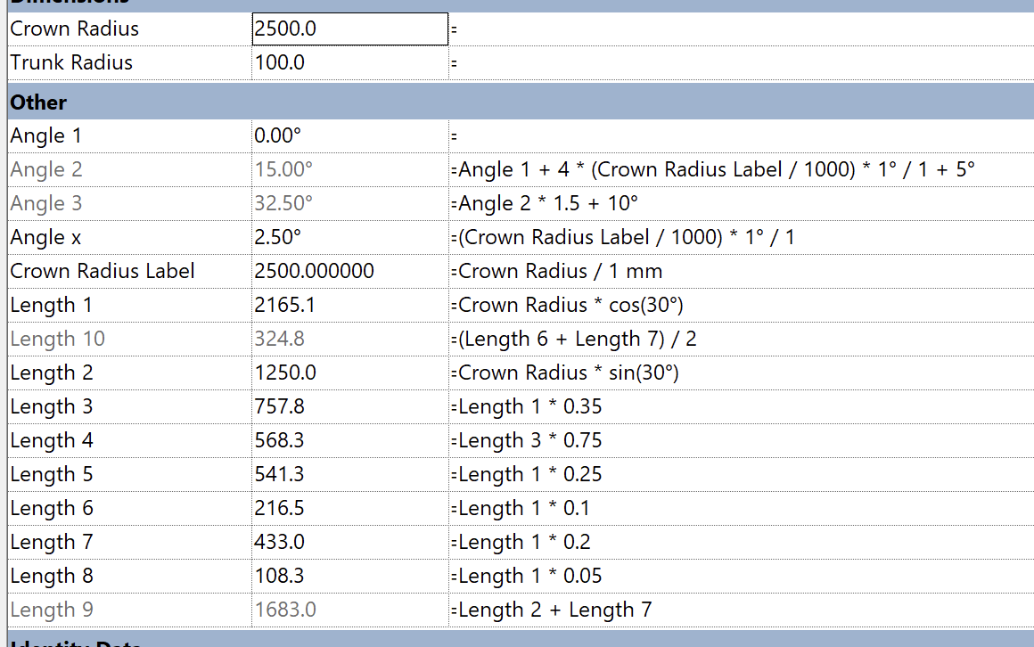
The origin dimensions are driven by the section DWG. You will need to measure the height and width of the tree. The width value is set as the default “Crown Diameter” for the plan DWG. This ties the plan and section DWG together.
Here’s how the three “origin” parameters need to be set up to match the section DWG. Add these values into the formula box to fix them in place.
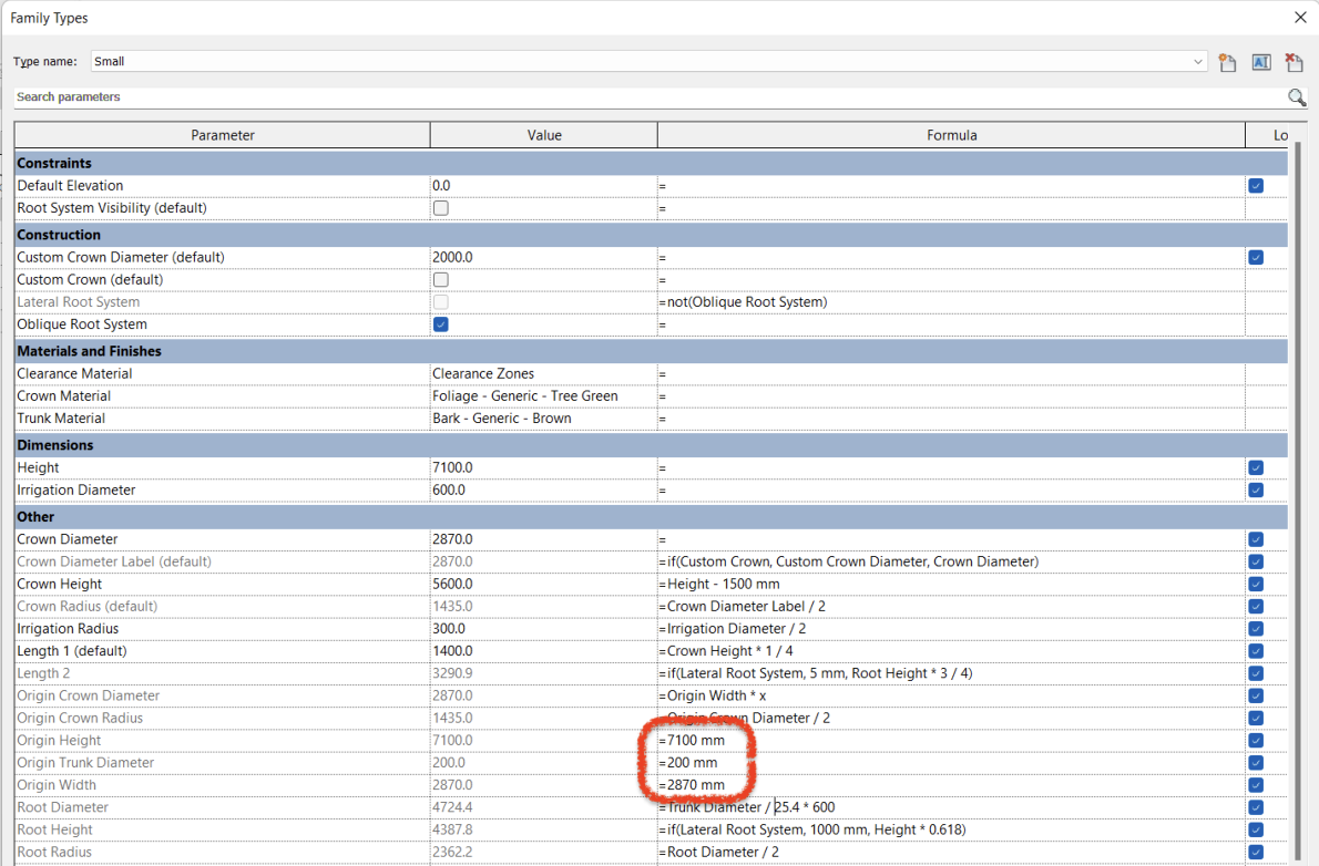
In this example of a columnar tree, the section DWG measures 2870 mm x 7100 mm (width x height). The original plan DWG diameter is 2810 mm.
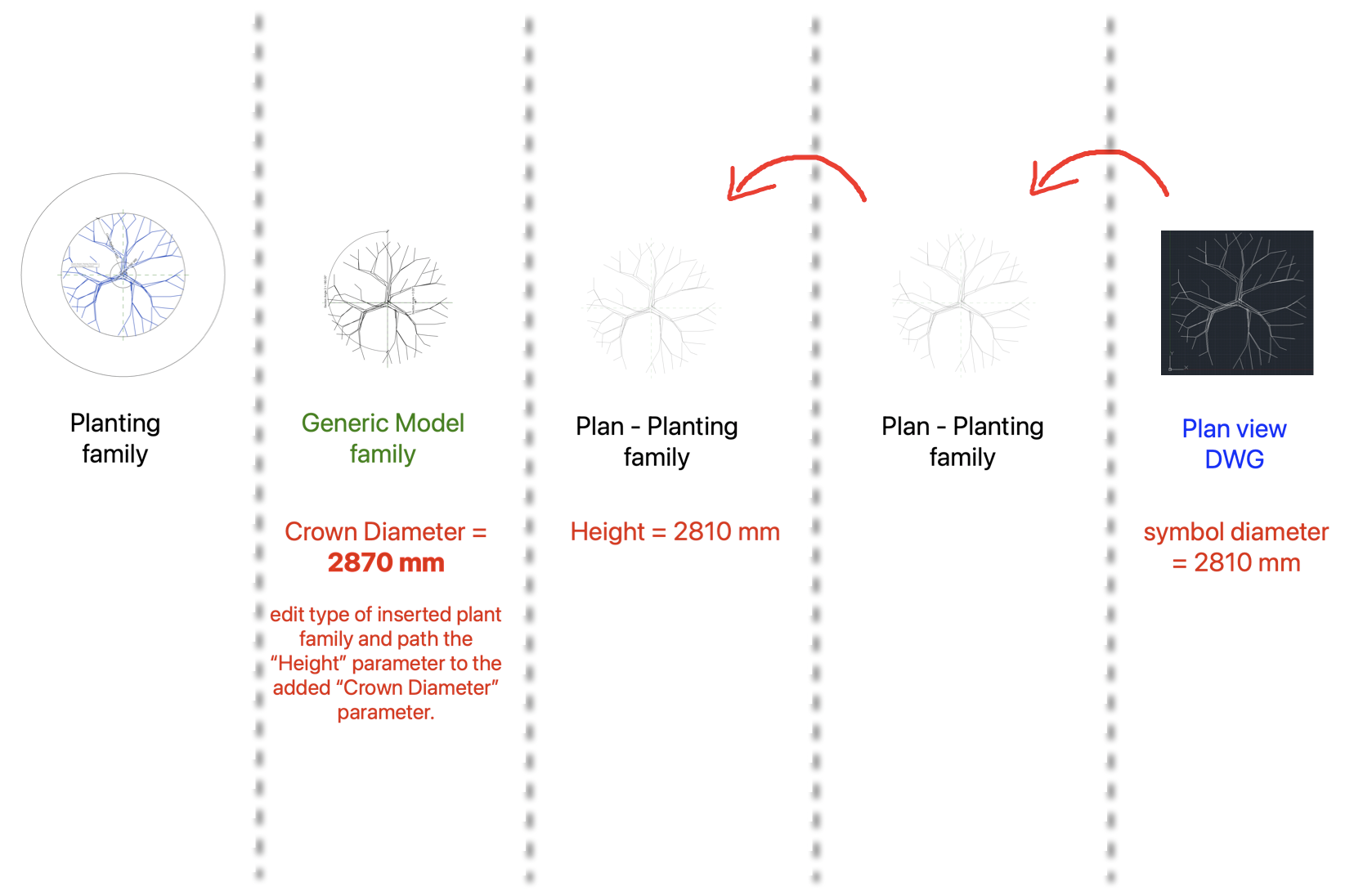
The Generic Model placeholder family is an important nesting step. It allows us to have separate control over the Crown Diameter and Height values. The plan DWG is tied to the Crown Diameter and the section DWG is tied to the Height. Removing this step, and having just a series of planting families with independent Crown Diameter and Height, will result in both of these parameters affecting the growth of the family and unpredictable scaling.
Tips
1. The most efficient way to create a new family from this is to work backwards. You want to start from the main family first, rename the nested generic family to suit, and then edit from the project browser as shown below:
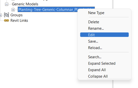
Follow this renaming and editing process throughout the nested layers.
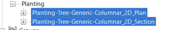
When you get to the last layer, which will be the planting family that has the inserted DWG file, you just need to load your own DWG files.
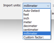
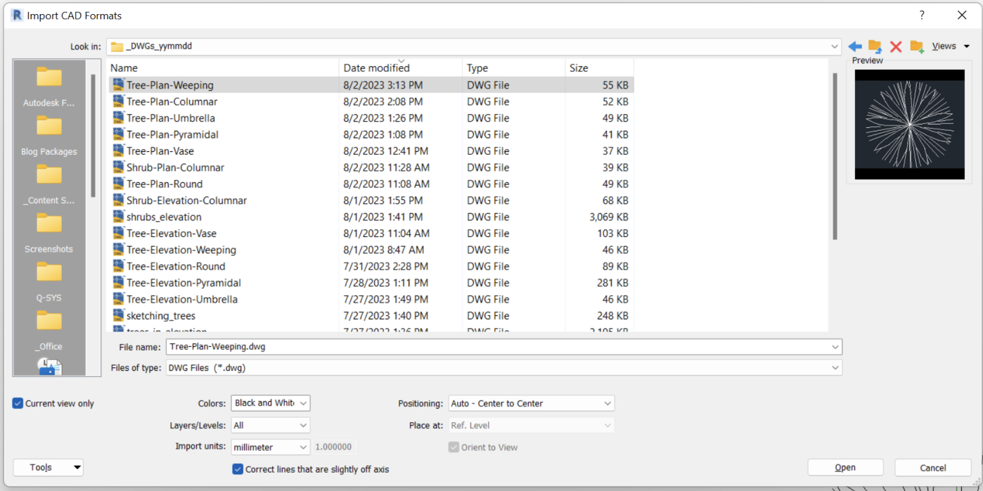
2. When importing the DWG files, I would advise setting the import units to “millimeter” and not “Auto Detect”.
3. We want to see the sectional DWG in 3D views. So, when importing the section DWG, make sure to untick the “Current View Only” box.
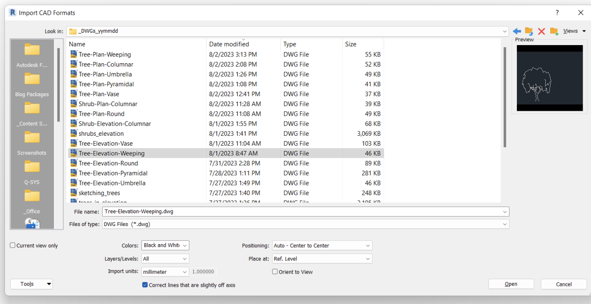
4. On the other hand, we only want to see the plan DWG in plan view. So make sure to tick the “Current View Only” box when importing the plan DWG.
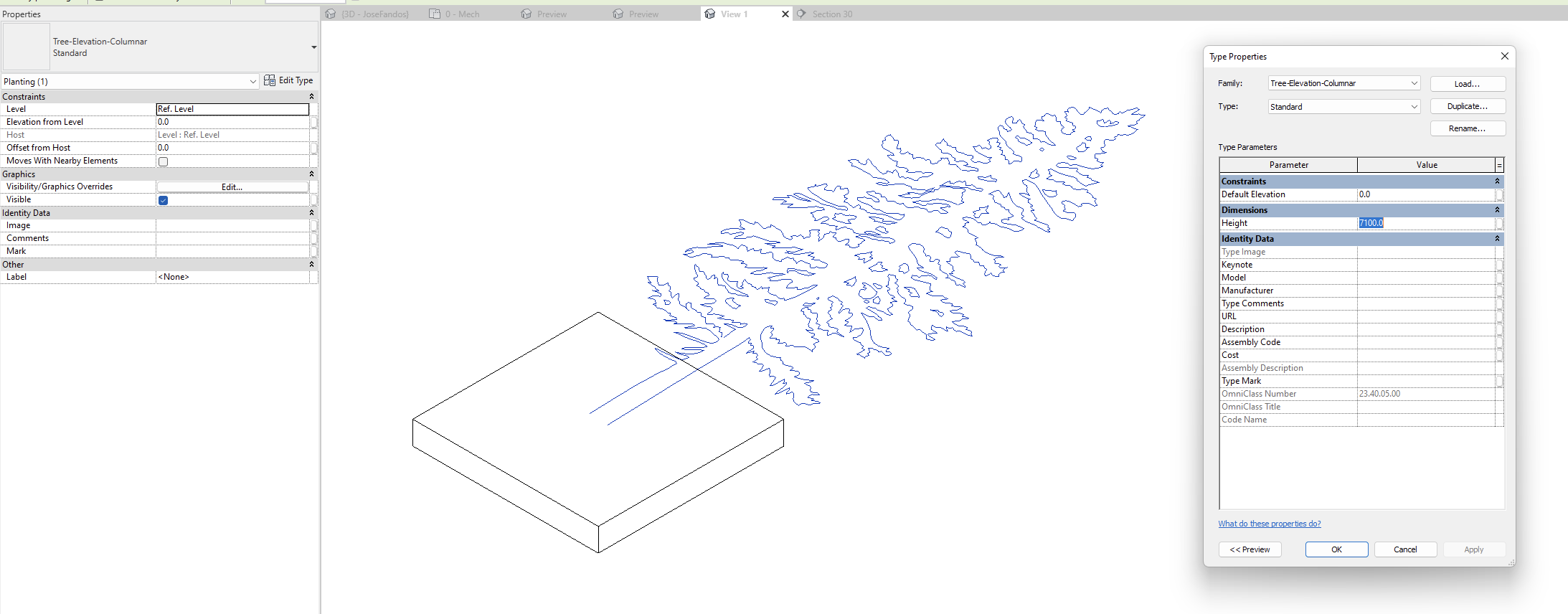
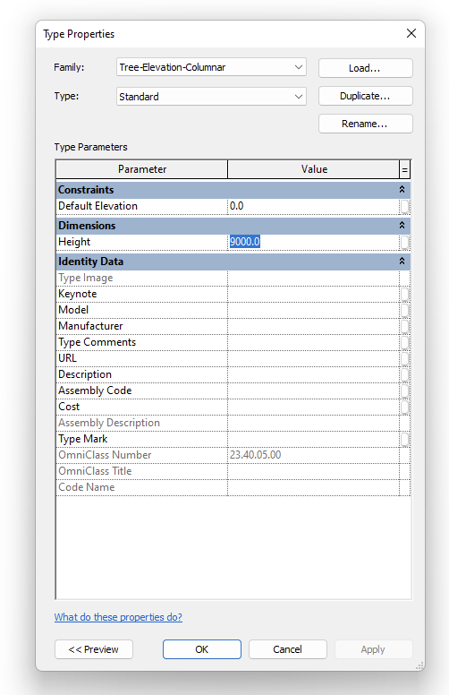
5. Edit the nested type and ensure its Height value is equal to the origin size. Otherwise, you will find the scaling in a project to be incorrect.
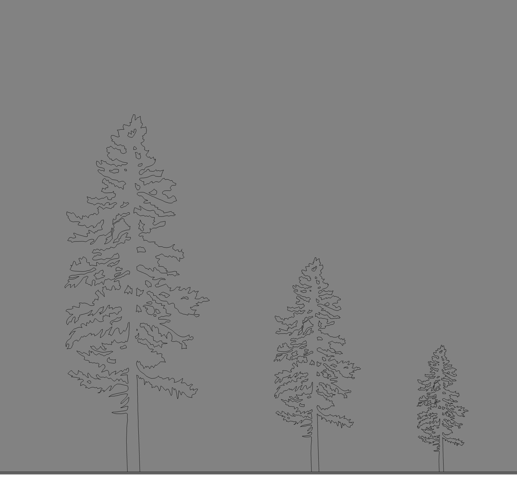
In the example below, the sectional DWG origin height is 7100 mm. The following three images show the nested type set to this value. In the project, the DWG has exactly the same height as the 3D geometry.
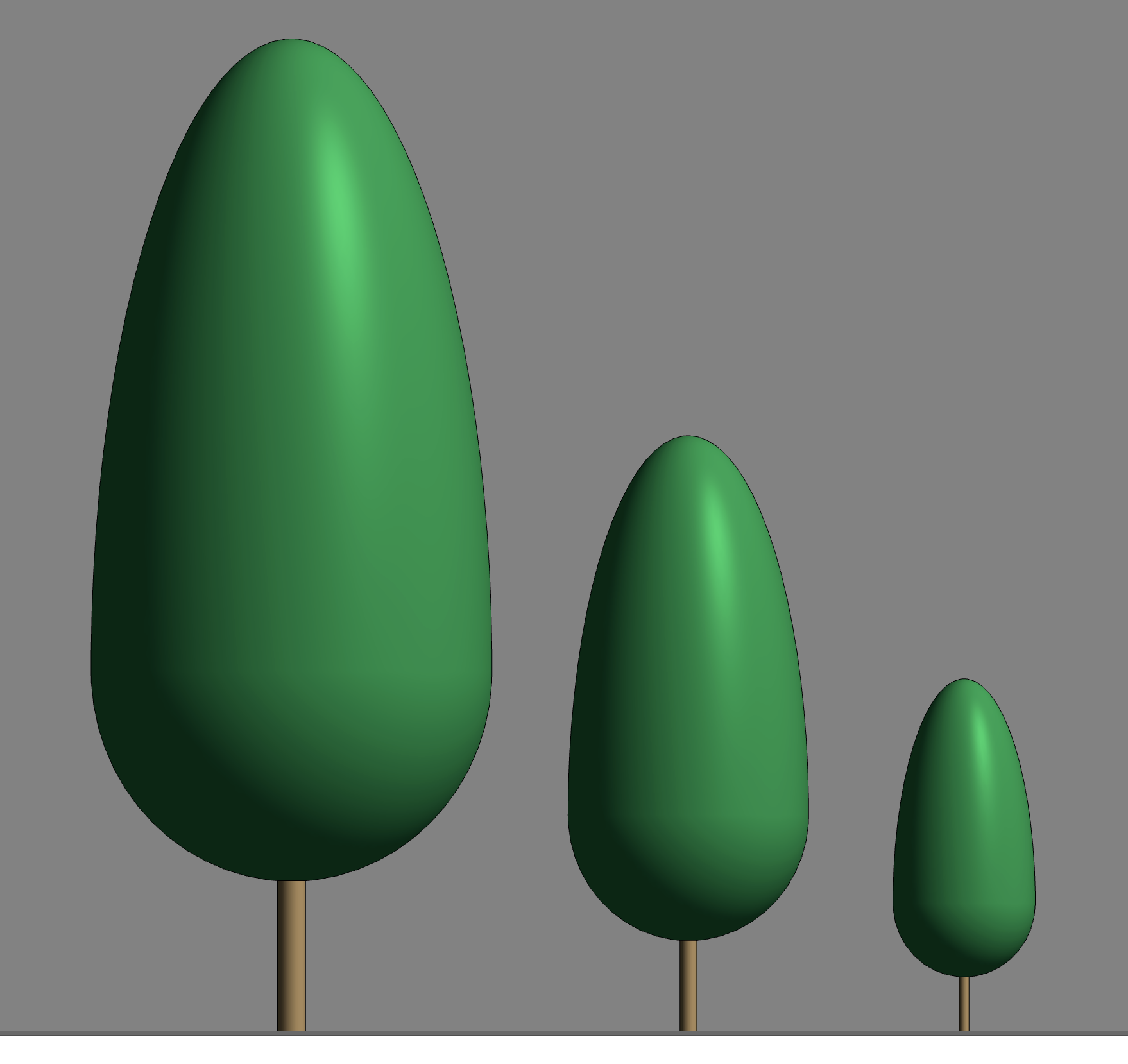
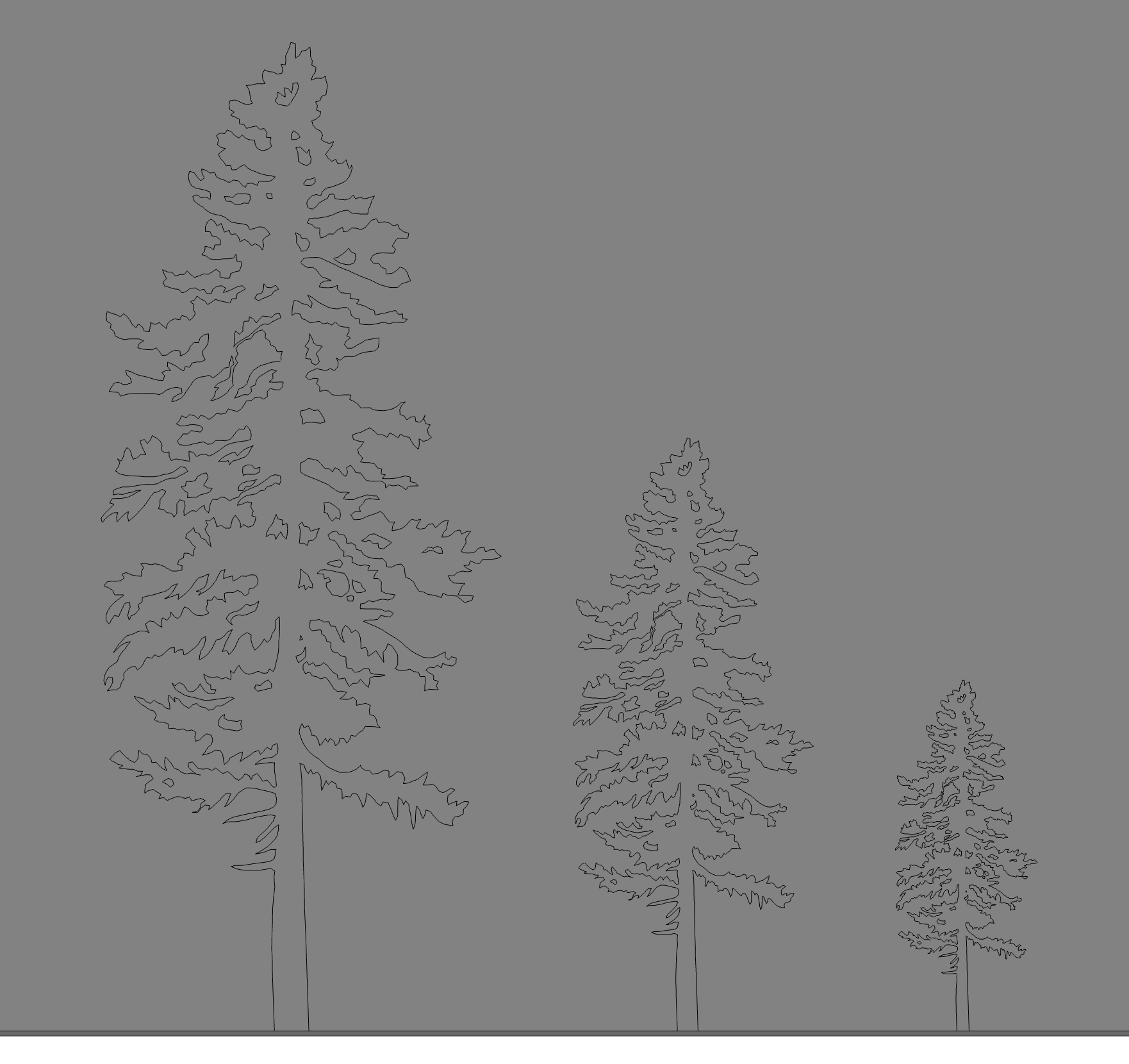
Elevation in medium level of detail (left). Elevation in a fine level of detail (right).
By contrast, if we change the Height value for the nested type to 9000 mm, which is larger than the origin value, the result in the test project is that the DWG section showing in fine LOD is now smaller than the geometry showing in medium LOD.

Our planting families are designed to be very flexible. As long as you replace the imported DWGs correctly and follow our tips, you’ll be able to create any tree or shrub. In addition, the families’ metadata allows for precise scheduling and confirmation that the correct plants are being used in a project.
If you haven’t done so already, check out our free scalable planting families collection and subsequent blog.
That’s a wrap on our scalable planting families. If you have questions or feedback regarding this content, send us an email at support@kinship.io. We’re eager to hear your input!
.jpg)